


Students Guide to Printing – 48
190) What is a Gear?
A gear is one of the machine elements which has several teeth cut either around cylindrical direction or cone shaped surfaces and flat rack and pinion type, and in some gears the teeth cut in different angles.
They are responsible for equal rotations of the connected part besides regulating the rotations on the machine. The geared devices can change the speed, torque, and direction of a power source.
Two or more gears operating together one behind the other is called a gearbox. The most common gears fitted on the printing machines are:
- Spur gears
- Helical gear
- Double helical gear
- Rack and Pinion
- Bevel gears
- Miter gears
- Worm and worm gears, Screw gears and internal gears.
191) Various types of gears
Spur Gear:-
The most common gear is spur gear. The teeth on spur gears are straight and are mounted in parallel shafts. The spur gear, on which the teeth are cut parallel to the surface of the cylinder, generally requires a backlash gear to reduce play. Cylinders which run on the bearers, commonly use spur gears. This is a gear used to drive printing press rollers or cylinders in which the teeth are cut parallel to the surface of the cylinder. The spur gears can be classified into two main categories: External and Internal. The gears with teeth cut outside the surface of the cylinder are known as external gears. The gears with teeth cut on the internal side of the cylinder are known as internal gears.
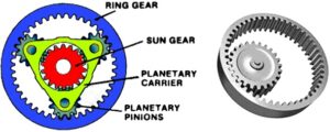
Internal gear:-
Internal gear is also called hub gear. Internal gear has its teeth cut in the internal surface of a cylinder or cones and meshes with spur gears or planetary pinions. Internal gears are often used in applications involving planetary gear drives and gear couplings.
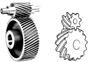
Helical gears:-
Helical gears operate more smoothly and quietly compared to spur gears due to the way the teeth interact. The teeth of a helical gear are set at an angle and take the shape of a helix. One of the most noticeable benefits of helical gears over spur gears is less noise, especially at medium to high speeds. The advantage that helical gears provide over spur gears is the ability to use with either parallel or non-parallel (crossed) shafts. They have better teeth meshing than spur gears.Helical gears’ teeth have a larger contact ratio because their angled teeth result in more gradual contact with less friction. These gears are perfect for applications that require quietness, or those that are sensitive to vibration.
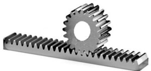
Gear Rack:-
Same sized and shaped teeth cut at equal distances along a flat surface or a straight rod is called a gear rack. A gear rack has straight teeth cut into one surface of a square or round section of rod and operates with a pinion, which is a small cylindrical gear meshing with the gear rack. Generally, gear rack and pinion are collectively called ‘rack and pinion’.
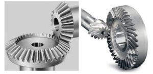
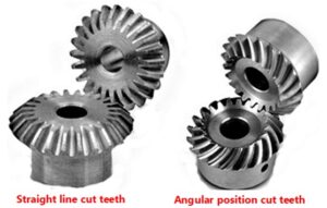
Bevel Gear:-
Bevel gears have a cone shaped appearance and are used to transmit force between two shafts which intersect at one point. A bevel gear has a cone as its pitch surface and its teeth are cut along the cone. Kinds of bevel gears include straight bevel gears, helical bevel gears, spiral bevel gears, miter gears, angular bevel etc.
Miter Gear:-
This belongs to bevel gear family. Miter gears are one type of bevel gears where the two rotational axes intersect and have equal numbers of teeth. They are used to change the direction of power transmission without changing speed. There are straight miter and spiral miter gears. The teeth is cut either as straight line or in angular position both female and male matching with each other.
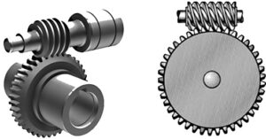
Worm Gear:-
A worm gear consist of a shaft with a spiral thread that engages with and drives a toothed wheel. Worm gears are an old style of gear, and is a screw butted up against what looks like a standard spur gear with slightly angled and curved teeth. They can be used as speed reducers in low- to medium-speed applications.
It changes the rotational movement by 90 degrees, and the plane of movement also changes due to the position of the worm on the worm wheel. They are typically comprised of a steel worm and a brass wheel.
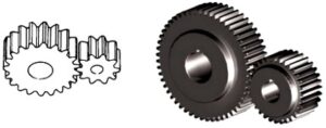
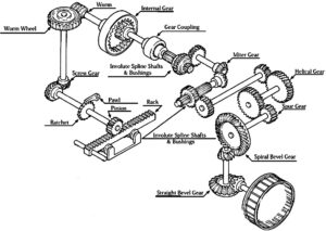
General illustration below to understand various gears


Recent Comments