


Analysis on Theory and principle of inking unit on an Offset machine
Analysis on Theory and
principle of the inking unit
on an Offset machine
Written by : N.R. Jayaraman
What is the theory and principle behind configuration of the inking unit with multiple rollers on an Offset machine? This question has been asked by many over period of time though everyone know that the basic function of the inking unit in an Offset printing machine is to supply uniform, thin layer of ink to the image on the plate which transfer it to the substrate on which the prints are taken via the rubber blanket.
One question can be certainly asked. Is it not possible to ink up the plate with two or three rollers alone instead of having multiple rollers in the inking unit on an Offset machine?
Those who understand the theory of inking will realize that with a set of two or three ink rollers, if the Offset plate is inked, the image will receive fairly thicker layer of ink film, try in any manner even with a very thin layer of ink put on the charging rollers. It will only leave thin and thick layer of ink instead of uniform layer of ink because the ink released from the duct cannot be maintained to supply thin, uniform layer of ink by two to three rollers alone for the entire printing process. The ink applied over the plate has to be very thin, lesser than micron thickness, evenly spread, and well ground which cannot be practically achieved with just two or three rollers because of the rheological properties of the ink. The inking in an Offset machine is somewhat similar to rubber stamping process in which two smooth contact mediums touch each other to transfer the print in smooth transition.
Unless the slightly tacky ink put in the ink duct travel through few rollers, surface ground and the tack loosened to the working level, laying of a thin film of ink on Offset plates cannot be achieved. If the ink tack is not loosened, then the plate will not receive thin layer of ink unlike Letterpress printing where the laying of ink is slightly heavier than Offset printing.
Each of the inking rollers- varying in diameter and made up of different metals or material beginning from the duct (fountain) roller to the form rollers in an Offset machine have their own function. An analysis of the configuration of the inking system suggests that the configuration has been designed in such a manner that uniform thin layer of ink estimated to be in the range of around 1.005 µm is placed over the image areas on the plate which transfer 1.003 µm inked image to the blanket, which in turn transfer approximately 1.000 µm of ink to the substrate on which prints are taken.
![]()
But in the process of transfer of thin layer of ink from the ink duct through chain of rollers, form rollers, plate, blanket and finally to the substrate on which prints are taken, a negligible part of the ink is held back by the mediums transferring the ink from their body to the next medium on account of an technical factor called ink splitting.
The implication arising out of the ink splitting theory is the main factor for the configuration of the inking unit with multiple rollers on an Offset machine. The process of ink transfer at various points and the implications of the ink splitting are explained in detail below. The contact transfer process points and the rheological properties of the ink are important factors connected to the ink splitting tendency besides the micro metallic properties of the metal plate and the construction of the rubber blanket used.
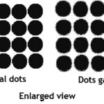
What is Ink splitting factor? The term virtually means the layer of ink at the point of contact and transfer gets split into two layers –actually transferred part and residual part- which happens because of pulling pressure or picking velocity of the ink after the ink layer is laid on to the substrate and the medium of transfer lifts off.
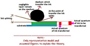
More tacky or viscous the ink, greater will be the velocity and when thicker layer of ink film is laid, then too the tendency of the ink splitting will be higher. Few of the main properties of the ink which cause it to happen include Viscosity of the ink, Ink Tact and the Adhesive added in the ink for adhesion to the substrate or for drying over the substrate.
See below one of the most commonly configured inking unit on an Offset machine with several solid rollers in varying diameters and made up of different material like Steel, copper, Brass and hard Synthetic resins/Urethane coated metallic material.
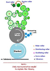
The present analysis is based on the above illustrated model of inking system, found configured on most of the Offset machines. However the diameter, material and placements of the solid rollers may vary on the machines offered by different manufacturers.
The important ink transfer points on an Offset machines are (a) Ink duct to the ductor roller (b) Ductor roller to the chain of rollers (c) Chain of rollers to the form rollers (d) Form rollers to the plate (e) Plate to the blanket and finally (f) Blanket to the substrate on which prints are taken.
In order to leave a thin layer of ink film over the image areas of the plate, multiple roller chain consisting of small and bigger dia rollers, made of different materials have been engaged through which the thin layer of ink supposedly in the range of around 1.005 µm or so is transferred on the printing plate through a set of rollers called form rollers which is in direct contact with both the chain of inking rollers as well as the plate carrying the image. This is the prime point where the thin layer of ink supposedly in the range of around 1.010 µm is maintained over the form rollers. How to feed such a thin layer of ink from the duct to the form rollers rests on the kind of configuration of the inking unit. Also reason for maintaining ink layer of 1.010 µm over the form rollers is to be understood.
If the ink is transferred from the duct directly on to the form rollers without intermediate chain of inking rollers, it will certainly be not possible to maintain the thin layer of 1.010 µm ink over the form rollers since the ink has to be well ground to slightly loosen the initial tack of the ink put in the ink duct and to bring it to the working level. Secondly the ink has to evenly and uniformly spread over the entire length of the rollers, ink layer carried by the rollers remain free of extraneous particles or dry skin of ink which forms due to one of the rheological properties of the ink which has the tendency to harden the top layer of the ink in the ink fountain to leave a thin layer of dry skin over the ink in the duct when constantly exposed to the room atmosphere in press run.
In order to prevent the top layer of the ink forming a thin dry skin over the ink in the duct, the ink in the duct is manually or by other means like automatic ink agitators, pushed and mixed end to end in the ink duct at frequent intervals. This action prompts slightly thicker flow of ink than normal flow from the duct whenever the ink is pushed. A thicker layer of ink cannot be allowed to get transferred on to the ductor roller which will transfer it to the form rollers. The thicker layer of inking will affect the quality, sharpness and appearance of the print besides causing few other technical problems like slower drying of ink over the substance on which prints are taken which will also come in the way of next colour printing. Hence the form rollers cannot be allowed to directly receive the heavy inking from the duct.
In order to get good print, it is necessary that the inking system is designed in such a way (a) to ensure constant supply of ink from the duct (b) to ensure that the constant supply is uniform, even, thin and free from dry particles (c) to ensure that the same level of thin ink layer is maintained from print one to the last print even after the form rollers get recharge at the end of inking the image areas on the plate.
The above conditions cannot be achieved with just one or two rollers besides ductor roller receiving the ink from the duct. Direct transfer of ink to the form rollers will leave fairly heavy inking. Therefore as said earlier, to ensure smooth flow of ink to the form rollers, additional rollers are required in between the form rollers and the ductor roller to act as transfer rollers to counter technical problems arising out of ink splitting. The role of ductor roller is also very important in the ink chain to ensure that the chain of rollers and the form rollers maintain the expected level of ink layer on their surfaces. The importance and role of ductor roller will be explained later.
Now the question comes (a) how many intermediary rollers will be needed to evenly charge the form rollers (b) what is the role of each of the rollers in the chain of rollers (c) what is the extent of ink release required from the duct (d) what is the extent of ink layer to be maintained on the rollers midway traveling towards the form rollers and (e) finally how much ink layer is required to be maintained at various points of transfer to ensure that the form rollers get recharge only to the extent it transfers the ink from its body on to the image on plate before getting recharged for next inking and (f) the configured roller chain should also meet the needs of all kinds of print done on that machine.
Taking into consideration all factors detailed above, the points of transfer of ink at various points have been carefully studied one by one along with the implications of the ink splitting. The analysis begins with the point of transfer to the substrate where the minimum layer of ink in the range of 1.000 µm is expected to be laid over and thereafter discuss every points of transfer above them.
A: Point of Ink transfer
Plate to Blanket and Blanket to the Substrate
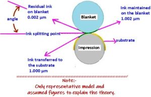
Actually point of contact in transfer of ink between the blanket and the substance is the last one in various points of contacts. In the act of continuous process of ink transfer, every medium that transfer the ink in each of the points of transfer is influenced by the ink splitting factor. Since minimum layer of ink in the range of 1.000 µm is expected to be laid over the substrate, slightly higher level of ink layer than 1.000 µm is to be carried by the blanket and the plate keeping in mind the ink transfer required on to the substrate. This additional layer of ink is essential to compensate the ink splitting factor.
Some studies have indicated that a thin layer of ink in the range of 0.002 µm to 0.003 µm is retained by two of the transferring mediums-plate and the blanket- at their point of ink transfer on account of ink splitting tendency. This therefore suggests that beyond the actual ink transfer required for the substrate the blanket need to keep additional 0.002 µm over its surface beyond 1.000 µm which totals to 1.002 µm and the plate additional 0.003 µm layer beyond 1.002 µm which is necessary for the blanket. This therefore implies that the plate need to maintain 1.005 µm layer of ink and blanket 1.002 µm layer of ink on them throughout printing.
Thus after the plate gets inked up, the entire 1.005 µm layer of ink held in the image areas on the plate is not transferred on to the blanket, but a negligible layer of ink say 0.003 µm layer of ink is held back on its surface while 1.002 µm layer of ink is only transferred to the blanket. In the continuous process of contact between the plate and the blanket, in addition to the ink splitting factor, certain unexplained static too add up to the cause of retention of ink over the transferring medium.
![]()
The blanket which receive approximately 1.002 µm layer of ink, in turn pass on the inked image estimated to be in the range of approximately 1.000 µm layer of ink to the substrate on which the print is made and here too due to the act of ink split approximately 0.002 µm layer of ink is retained by the blanket because the transfer here is smooth. Even though the transfer of ink is in smooth compressed contact process, a negligible percentage of ink intrude into the blanket due to the tendency of absorption of the rubber based material besides the act of ink split at that point. The intruded ink slightly hardens the image areas on the blanket, which of course is not visible to the naked eye compared to the compressed areas on non-image areas in the blanket. Those negligible hardened areas on the blanket also contribute to the ink split because the ink split is higher when two smooth surfaces contact each other.
Therefore in order to lay a thin film layer of 1.000 µm ink on to the substrate, approximately 1.002 µm layer of ink or so need to be maintained by the blanket while 1.005 µm layer of ink or so is need to be maintained by the plate and not beyond when printing is on. If too much of ink is transferred on the plate or the blanket, then the sharpness and beauty of the reproduction aimed at will be lost. Similarly lesser ink will also mar the appearance of the reproduction.
Therefore taking into consideration the thin layer of ink required and the implication of ink split at this point of transfer, more rollers becomes necessary to tone down the thickness of the ink and even out the flow of initial ink discharged from the ink duct before the ink reach the form rollers.
B: Point of Ink transfer
Form rollers to the Plate
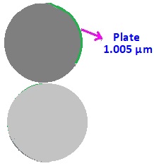
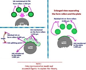
The crucial point of contact above the Plate cylinder is the form rollers from which the plate receive the ink. This is the most important point of contact which is last but one point of contact where the ink transfer takes place, and the implication of ink splitting plays the major role. As said previously, in order to lay a thin film of ink say 1.000 µm on to the substrate, approximately 1.002 µm layer of ink or so is need to be maintained on the blanket and 1.005 µm layer of ink or so is need to be maintained over the plate. Therefore the form rollers need to keep a little over 1.005 µm layer of ink as required by the plate and then continue to get ink recharge from the chain of rollers before inking next.
In this continuous process of contact between the form rollers and the plate, due to the rheological properties of the ink, the ink splitting occurs with more velocity compared to the point where the blanket and plate exchange ink between them. As said earlier similar to the act of the plate and the blanket both of which hold back negligible layer of ink on their surface while transferring the ink from them, the form rollers too hold back around 0.005 µm layer of ink on their surface, a little more than the retention of ink held by the plate at the point of contact. Therefore the form rollers require to maintain a minimum layer of 1.010 µm* ink (*1.005 µm layer of ink required by the plate + 0.005 µm layer of ink to compensate higher velocity of ink split = 1.010 µm layer of ink) on their surface.
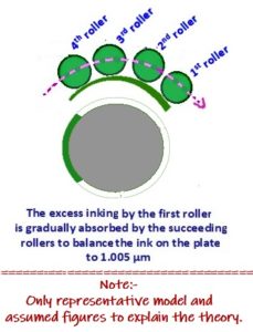
One always find more than three form rollers fitted in the inking unit to supply the ink to the plate. There is specific reason for it. The plate cylinder which hold the image on it has around 20% gap in the in the circumference of the cylinder housed with clamps or pins for fitment of the plate. The first in the set of form rollers cross the gap to ink up the plate afresh every time after one circle of inking is done though without a jump or bump at the edge of the gap. Since the form rollers inking the plates are generally more than three, some studies indicated that while the first form roller touching the plate after crossing the gap tend to transfer slightly heavier ink while the succeeding rollers that follow absorb part of the heavy inking and even out the ink layer to the level say 1.005 µm required by the plate. It is because of this natural act enacted by the succeeding form rollers, it will be interesting to see that even though the form rollers are in contact with the rest of the roller chain during inking the plate, they are not overloaded with ink at each end of revolution.
Let this be explained further. The form rollers carrying ‘x’ layer of ink, when roll over the plate to ink up the image areas is in contact both with the image as well as non-image areas on the plate. The ink transfer process from form roller to the plate is not wipe out process of transfer but transfer by kiss touch or roll on process. In the continuous contact between the roller and plate which has areas to be inked and non-areas to be protected with a thin layer of water that repulse the ink in the same plane, the rollers touching the non-image areas of plate turns partially blind in continuous fictional contact with water (dampening roller) thereby resisting full ink recharge on those areas. Therefore the ink recharge takes place effectively only in those areas where the form roller has residual 0.005 µm layer of ink retained by them while in the non-image areas the roller partially resists recharge and maintain the same level of 1.010 µm layer of ink.
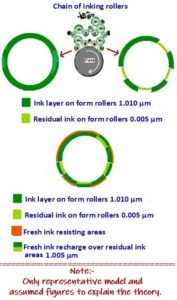
Therefore taking into consideration the retention of 0.005 µm of residual ink over the form rollers and 1.005 µm ink to be supplied to the plate, the configuration of the inking unit has been well designed to ensure that the form rollers maintain 1.010 µm layer ink constantly.
C: Point of Ink transfer
Chain of ink rollers to the Form rollers
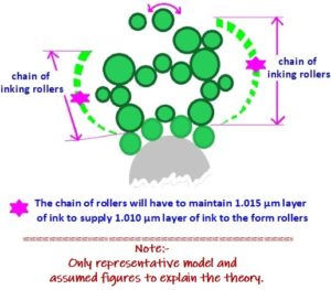
The next point of contact for the form rollers is chain of inking rollers which consists of rollers in various diameters and made of different material. The point of contact between the chain of rollers to the form rollers is the second point of contact below the Ink duct from where the main supply of ink is made. As said earlier, it is necessary to keep 1.010 µm layer of ink on the form rollers which gets the ink feed from the chain of inking rollers positioned above. The question is how much ink will have to be maintained by the chain of rollers which takes the supply from the ink duct? Since all of them are also governed by the ink splitting theory and affected by the some of the rheological properties of the ink, it is necessary that the roller chain has to maintain a little over 1.010 µm layer of ink as maintained by the form roller besides another 0.005 µm layer of ink for other reasons including ink splitting, ink drying in atmospheric changes in press room etc. Thus it becomes necessary that 1.015 µm layer of ink need to be maintained on the chain of rollers. At the same time they should not carry more ink than what is necessary.
At this point of inking i.e. between the chain of inking rollers and the form rollers, different acts of ink transfer takes place. The chain of inking rollers has oscillator rollers also called Drum rollers, Vibrators, Riders and Distributing rollers etc each of which are important in their own manner. The function of those rollers in the ink chain is not only to receive the ink from the ductor also called doctor roller either directly or through other rollers, but also to get it spread evenly on their surface besides toning down the thickness of the ink film as the initial receipt will be slightly heavier and tackier from the ductor roller.
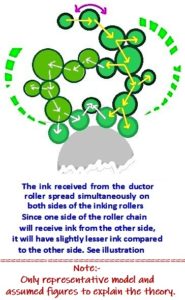
If you carefully look at the structure of the rollers, generally one can see many oscillator rollers which move laterally as they rotate and occupy different positions within the ink roller chain. While one of the oscillating roller is in direct contact with the doctor roller to receive and pass on the ink, the others are engaged in the act of mixing up the ink well, get it spread evenly over their body, pass on some to the other rollers in the ink chain so as to ensure that the thin ink film finally reach the form rollers. In this process of ink transfer the ink received directly at one end of the chain of rollers gradually transfer the ink to the other end of rollers of the ink chain before taking them down to the form rollers. See the illustration below to understand how the ink gets spread simultaneously on both sides of the chain of rollers.
In order to maintain an average 1.015 µm layer of ink all over the chain of ink rollers, the first roller that take fresh supply of ink from the ductor roller in regular intervals pass it on to the next line of rollers which spread them to the other rollers in chain in the same speed. However in this process of transfer only part of the ink on them is transferred to the other rollers as they too have to retain some on them. In order to maintain an average 1.015 µm layer of ink over the body of the chain of rollers from which they will transfer 1.010 µm layer of ink to the form rollers, it is necessary that in initially the chain of rollers should receive a slightly higher quantum of ink from the ductor roller. Therefore the ductor roller has to receive 1.015 µm layer of ink plus another few µm layer of ink say 0.007 µm totalling to approximately 1.022 µm layer of ink from the duct roller to feed a major part of it to the first roller in the chain of roller and also to compensate for the ink splitting and other rheological properties of the ink. There is another reason for receiving and transferring higher layer of ink. Since the ductor roller does not continuously rotate along with the first roller in the chain of rollers and skip one rotation before each recharge it has to transfer a little over 1.015 µm which is maintained by the entire team of chain of rollers.
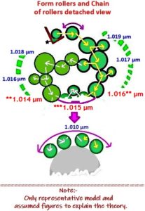
As said earlier the slightly higher layer of ink released by the ductor roller say in the range of 1.019 µm, first received by the first roller in the chain of rollers quickly share it to all other rollers in almost Zig zag manner and therefore the layer of ink on the chain of rollers will always be lesser than the actual receipt of 1.019 µm because the layer thins down before the ink feed reaches the form rollers. Moreover in the transfer process of ink by the first roller in the chain of rollers, a major part of the ink received is fast delivered to the immediate rollers that are below them while the ink that gets routed to the other side is slower and slightly thinner, but due to the designing of the inking unit the ink layer get mixed up midway in the roller chain to ensure that the chain of rollers in both sides together sharing the 1.019 µm layer of ink maintain 1.015 µm at the last leg of chain of rollers (**1.016 µm + **1.014 µm =1.030 µm ÷ 2 = ***1.015 µm) to supply 1.010 µm layer of ink to the form rollers. If for the sake of argument the originating supply of ink from the ductor roller in thickness of 1.022 µm is maintained on all the rollers down to the form roller, then the rollers will be flooded with more ink than what is necessary. See the illustration below to understand the theory.
D: Point of Ink transfer
Ink duct to the Chain of ink rollers via ductor roller
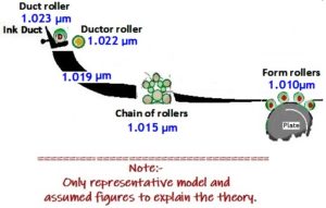
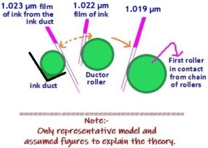
Now finally the ink release from the ink duct to feed the chain of rollers is actually the first point of ink transfer. Then the question comes as to what is the quantum of ink release needed from the duct? The broad based theory is that the initial release of the ink from the duct should be slightly heavier, but by the time it reaches the form rollers, it should have become thinner. Keeping this theory in mind and to constantly maintain a thin film of ink in the range of 1.010 µm on the surface of the form rollers, initial release of approximately 1.023 µm film of ink from the ink duct roller may be required to transfer 1.022 µm film of ink to the ductor roller which intermediately recharge approximately 1.019 µm film of ink to the chain of rollers after holding some layer of ink on its surface. When the discharged ink layer of 1.019 µm film of ink from the ductor roller continue to flow down, it becomes thinner and thinner and before the ink flow reach the last leg form it becomes 1.015 µm layer to supply 1.010 µm layer to the form rollers as shown in the illustration below.
The ductor roller’s rate of movement between the fountain roller and the oscillator (the first roller in contact from the chain of ink rollers) are generally adjustable and is commonly timed to the revolution of the plate cylinder. The length of time that the ductor roller is in contact with the fountain roller is also adjustable to control the quantity of ink flow from the duct. The length of time that the ductor roller is in contact with the fountain roller is called dwell whose action is also related to the rate at which the fountain roller turns to ink up the doctor roller. The faster it turns more surface area of the ductor roller is inked resulting in more ink reaching the plate. The function of transfer by the ductor roller is not continuous, but intermediate to ensure that the chain of entire rollers are able to continue to receive 1.019 µm film of ink from the doctor roller to share the ink on the entire rollers in the chain to ensure appropriate film of ink required by the form rollers.
E. Need for multiple rollers
The quantum of ink to be maintained in each points of transfer has been explained with figures based on certain studies and normally discussed and debated. Keeping in view all the factors stated in Paras A, B, C and D in mind, and in order to ensure smooth, uniform flow of ink from the ink duct to the form rollers, multiple rollers in varying sizes and diameters were found necessary to maintain a thin ink film flow which cannot otherwise be achieved with one or two rollers alone above form rollers.
One can ask as to why so many rollers are necessary? The ink received by the rollers should get well ground and spread evenly over their surfaces on way before reaching the form rollers. Due to the rheological properties of the Ink, there is always tendency of the ink getting mildly hardened or stiffened when continuously exposed to the room temperature as driers form part of ink composition and the tack of the ink need to be kept softened to the working level. In order to ensure that the ink does not harden of stiffened (becomes more tacky) more number of rollers have been kept which generate mild heat through fiction when the rollers touching each other rotate in high speed to take care of the above two factors. Offset ink turns to workable viscosity only after extensive grinding on rollers.
Distributors typically sit between two other rollers, such as oscillators, and move by surface contact with the adjacent rollers. Distributor rollers are responsible for mixing the ink to form a uniform layer. The rider (R), distributor rollers (Di) and the Vibrators (V) vibrating rollers which oscillate laterally help in grinding and mixing the ink well and spread the ink evenly and uniformly before they reach the form rollers in the form of a thin, uniform layer of ink for supply to the plate. The oscillating doctor roller moving at right angles is meant to intermittently stop the supply of fresh ink to the chain of rollers only to the extent of ink discharged on the image areas. Riders are typically connected to oscillator or distributor and function solely to condition the ink by grinding the ink well with the roller over which it sits so that the ink turns to workable viscosity.
Having the smallest diameter of all inking rollers, riders have the greatest number of rotations per minute, and they move due to surface contact with adjacent oscillators. Riders also collect various types of paper and ink debris. While the riders (rollers) over vibrating rollers keep grinding the ink, the vibrators keep moving either ways on the sides (oscillating) to evenly spread the ink and retain the same strength over their surface. Also the fresh supply of ink has to uniformly merge with the ink already on the rollers which is taken care of by the distributor rollers. With only two or three rollers this act is not possible to be enacted.
Besides the rheological properties of the Ink, the general micro properties of the substance on which the print is taken and the micro geometry of the metal plates used as image carriers and the blanket are other important factors that govern good reproduction which inter alia depend on the smooth transfer of ink from their surfaces which is possible only with a good chain of inking rollers laying a thin layer of ink.
In an inking unit one can see that the ink is fed intermittently via the doctor roller. The ductor roller receive a relatively thick ink film from the ink fountain roller and transfer part of this to the first roller in the chain of inking unit. The quantity of ink released from the Ink duct is determined by the duct blade opening, rotary motion (rotation) of the ink fountain roller, the frequency of the vibrator roller contacting the fountain roller, and the speed of the chain of inking rollers. Taking all of them into consideration, the best flowing chain of ink rollers have been configured by the manufacturers that suits the printing machine offered by them as the print depends on the very fine layer of ink laid on the substrate uniformly throughout.
There is another question. Why the structural design of the inking unit is designed consisting of several types and diameters of rollers some of which are hard rubber based, some steel and some copper. Cannot all rollers be uniform and made up of same metal or material?
Generally the materials meant for making the rollers must be oil receptive and repulse water (moisture) but at the same time they must also shed the oily ink from their surface. Hence the material meant for the inking rollers in an Offset machine is carefully selected. While the distributing rollers are bigger and made of metal, the riders and vibrating rollers are made up of hard material, smaller in diameter. The diameters and weight of the rollers made of steel, copper, bronze etc and hard synthetic material, in bigger and smaller sizes are carefully determined while designing to reduce the weight of the inking unit, reduce space occupied by them and for easy handling. Tough rollers are needed for grinding and spreading the ink though they may be lighter in weight. In some of the inking units additional riders rollers can also be seen fitted to smoothen the ink film on the rollers. Remember that all the rollers of the inking unit have the same circumferential speed as the plate and/or blanket cylinder and therefore continuous discharge and charge keep happening as the machine continues to print.


Recent Comments